1. INTRODUCTION
Macromolecular crystallography has become one of the most important applications of synchrotron radiation. On almost all synchrotron radiation rings with moderate and high energy around the world, there are beamlines dedicated to the study of macromolecular crystallography. In mainland China, there is a medium energy ring (2.2-2.8 GeV) at the Beijing Synchrotron Radiation Facility (BSRF) and a low energy ring (0.8 GeV) at the National Synchrotron Radiation Laboratory (NSRL) in Hefei, providing synchrotron radiation. Unfortunately, however, until now there has been no beamline at either of these two facilities to serve for macromolecular crystallography. For this reason crystallographers of our country only have been able to collect diffraction data only in the laboratory or, by going to the SR facilities abroad, such as Photon Factory. In order to meet increasing demand for data collection facilities, recently, a project to construct a beamline and station for macromolecular crystallography at the BSRF has been proposed. Here we will introduce some aspect of this project.
The BSRF was completed in 1991. As part of the Beijing Electron-Positron Collider (BEPC), the BSRF is a partly dedicated source, i.e. so-called first generation light source. The storage ring of the BEPC can be operated in parasitic and dedicated modes to provide synchrotron radiation for the BSRF. In the parasitic mode the accelerator works for particle physics, the emittance of electron beam is set as 390 mm rad, and the energy and current of electron bearn is about 1.55 GeV and 30 mA, respectively, so only synchrotron light in the soft X-ray region can be used. In dedicated mode the storage ring is optimized for synchrotron radiation with the emittance as low as 76 nm rad, and energy and current of electron beam increased to 2.2GeV and ~60 mA. However, the operation time for the dedicated mode is only 2-3 months per year.
2. PRELIMlNARY EXPERIMENT
In the recent running time (Nov.-Dec. 1998) of the BSRF, the electron bearn current and life time were increased to ~100 mA and 20 hr, respectively. In order to check the experimental conditions of both the light source and equipment for protein crystal diffraction, a test experiment was performed at the diffuse scattering station 4W1C.
The 4WIC is a branch line of 4WIB beamline introduced from 4Wl wiggler insertion device, a single period wavelength shifier with magnetic period length of 1.36 m, peak field 1.8 T and a gap of 66 mm, giving a critical energy of 5.8 keV (2.14 A). By an oblique-cut bent triangle Si(220) crystal, the X-ray beam with ~2mrad horizontal span angle is deflected from the 4WIB line while being monochromatized and focused horizontally into the 4WIC beamline. A cylindrical mirror then is used to focus the beam in the vertical direction and to suppress the harmonics of the X-rays. The double-focused monochromatized X-ray beam with wavelength 1.54 Å and energy resolution 4.4 x 10⁻⁴ is directed to the diffuse scattering experimental station and gives a focal size of about 0.5 * 0.3 mm2 at the sample position. The main equipment of the station is a Huber 5-circle diffractometer on a multidimensional movable platform, including a Nal scintillation counter and a one-dimensional position sensitive detector.
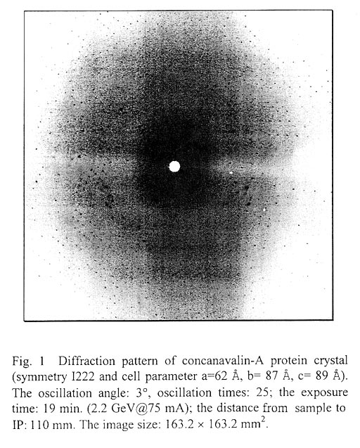
In our measurement, a flat-bed type film cassette was prepared and the FujiFilm imaging plate (IP) with dimension 200 mm x 400 mm was used as detector. The distance from the sample to the IP was set to be 110 mm. The c circle of the 5-circle diffractometer was employed as sample spindle oscillation axis, and for convenience of sample crystal alignment, a microscope display system was installed. By an XY-slits assembly the X-ray spot size at the sample was limited to 0.5 mm x 0.5 mm and an ionisation chamber was used to monitor the intensity of the incident beam. With the above conditions we used a concanavalin-A protein crystal (symmetry I222 and cell parameter a=62 Å, b= 87 Å, c= 89 Å) as test sample to collect diffraction data at room temperature by oscillation method. As shown in figure 1, we obtained a good diffraction pattern. However, it needed 15-20 min exposure time for one image with 3' oscillation angle when the current of the storage ring decayed from ~80 mA to 40 mA, which is only equal to that using the usual laboratory X-ray source.
3. FUTURE PLAN
The above-mentioned test shows the stability of the light source and beamline, and the lifetime of electron beam in the storage ring to be suitable to the requirements of data collection for protein crystallography, but the intensity of SR light from the 4W1 wiggler is too weak to take advantage of SR, and the equipment of data collection also needs further improvement in order to meet practical demands. So we propose a plan to construct a new beamline and station for protein crystallography at the BSRF. At the new beamline, special emphasis is on high photon flux incident on the sample, which involves light source and beamline configuration. Here we outline some of our considerations to these aspects.
3.1 Light Source
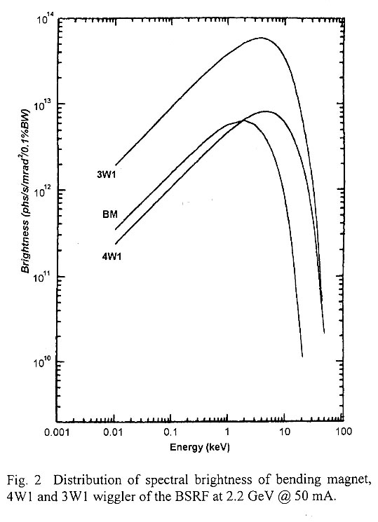
Amongst the existing three kinds of SR sources at the BSRF, bending magnet, 4Wl and 3W1 wiggler, the strongest one is 3W1 permanent magnet multipole wiggler. The spectral brightness of these sources at 2.2 GeV@50 mA are shown in figure 2, and from which it can be seen that at about 10 keV the 3W1 gives out SR with brightness nearly 10 times higher than that from the 4W1 wiggler. Since in the near future it is very difficult to get financial support to construct a new stronger insertion device light source in the BSRF, our design new protein crystallography beamline is planned to extract from the 3W1 wiggler source.
3.2 Beamline Optics
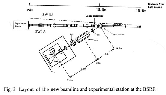
At present there are two beamlines (hard X-ray white beam line 3W1A (energy covers 3 to 30 keV) and soft X-ray line 3W1B (50 - 1500 eV)) on the 3W1 wiggler source, and from which it has been impossible to directly extract another beamline by space limit of the front-end. The horizontal acceptance angle of the 3WIA line can be extended from the present ~1 mrad to a few mrads, and by the side of the beamline there is enough space to set experimental hutch. So we decided to separate ~2 mrad of SR beam from this line by a curved crystal to satisfy the needs of the new macromolecular crystallography beamline (Fig. 3). The curved crystal, which is located 18.5 m from the source, serves to monochromatize and focus in the horizontal direction the separated beam. To obtain a photon flux as high as possible and reject the harmonics, it is necessary to focus the beam in the vertical direction by a cylindrical mirror, which will be located down-stream of the curved crystal, ~20 m from the source. The focus (sample spot) is set at ~23.1 m from the source. That means a 4:1 focusing scale for the curved crystal.
Because of the limited SR running-time (maximum 3 months per year) for the BSRF, it is impossible to allow the new beamline to share beam time with the 3W1A beamline, otherwise the available beam time will become very short. So in our design, a separation arrangement of the new beamline and beamline 3W1A is adopted. As shown in figure 4, the bent crystal (monochromator) only intercepts part of the white beam being fed into the 3W1A line from up-strearn and deflects it into the new beamline. The remainder will pass directly down-stream to the 3W1A line, so that these two beamlines can be operated simultaneously.
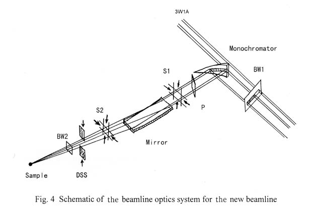
Apart frorn the curved crystal and cylindrical mirror shown in figure 4, the optical system of the beamline includes the Be windows, slits, shutter and BPM (bearn position monitor). In the following, we will mainly discuss the curved crystal and cylindrical mirror.
3.2.1 Curved-crystal
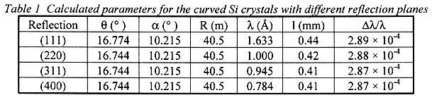
For the above beamline configuration, the deflection angle 6 of new beamline from the 4W1A line depends on the Bragg angle e of the curved crystal (δ=2θ), so it is very difficult to change continuously the wavelength of the monochromatic beam through the variation of O angle. In fact, for routine data collection, X-rays with a wavelength of 1 A should be able to satisfy the needs of most experiments. In order to guarantee large enough space between the new beamline and the 4W1A line to place the experimental hutch, we selected Si(220) as the curved crystal and will fix its Bragg angle at Θ=16.774°. That gives monochromatic X-rays with 1 Å wavelength. The Si(1 1 l), (3 1 1) and (400) crystals also will be prepared for the requirements of some special experiments. The wavelengths corresponding to these crystals are listed in Table 1 .
From the beamline geometry, we calculated some of the main parameters of the curved crystals, namely asymmetric oblique-cut angle α, curvature radii R, spectral resolution △λ/λ and horizontal width 1 of focal spot, and they are summarized in Table 1 .
3.2.2 Cylindrical Mirror
Consider a Pt coated cylindrical mirror with area 800 mm x 80 mm. With a
glancing incident angle Θg=5 mrad, we calculated the reflectivities
of the mirror for the fundamental and first
harmonics at 1 Å and 0.784 Å. These are
shown in Table 2. These demonstrate that
this incident angle can basically meet the
requirements of both the fundamental wave
reflection and the harmonic rejection. According
to the focus condition, the curvature radii
of the mirror is calculated to be ~1073.6
m, and the focal spot size in the vertical
direction is about 0.59 mm. 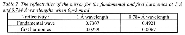
3.2.3 Estimate ofthe Photon Flux at the Sample Position
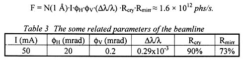
When the storage ring is operated at 2.2 GeV, the photon brightness from the 3W1 wiggler at 1 A is

Some related parameters of the beamline are summarised in Table 3, where I is the electron current of the storage ring, and ΦH and ΦV are respectively the horizontal and vertical angles accepted by the beamline. The photon flux F at the sample spot can be estimated as below
3 3 Experimental Station
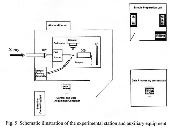
The experimental station (shown in figure 5), mainly includes a camera system (including shutter, collimation system, goniometer, sample microscope observation system and 2-dimensional detector system), sample cooling system, air conditioner system and computer controlling system. Besides the above instruments, a new sample preparation room and a data-processing workstation (including 1-2 SGI workstations) are necessary.
In our design, not only diffraction data can be routinely collected by the oscillation method with CCD or IP detector, but also high-resolution data for large cell dimension crystals can be collected with a Weissenberg camera and IP system.
4. ACKNOWLEDGEMENT
First of all the author would like to thank Professor N. Sakabe and Dr. K. Sakabe for their concern and help with this project. Thanks also to Professor X.M. Qian of Peking University for providing the protein sample, to Ms. Wenli Zheng, Mrs. Peng Liu and Qianjie Jia for assistance in the test experiment. Finally, the author especially thanks Professors Dingchang Xian, Yonglian Yan and Xiaoming Jiang for their support of this work.
【要旨】
Beijing Synchrotron Radiation Facility(BSRF)において、高分子結晶学用のピームラインとステーションを建設するプロジェクトが提唱されている。光源、ビームラインの光学系、そして実験用ステーションに関するいくつかの物理学的検討をここで示す。新しいピームラインのシンクロトロンX線は、マルティポールウィグラーライン3W1Aから分割され、湾曲シリコン結晶モノクロメーターにより単色化、水平方向にフォーカスされる予定である。プラチナでコートされた円筒形のミラーが、単色化されたビームを垂直方向にフォーカスするのに用いられる。湾曲結晶モノクロメーターとミラーを最適にデザインすることにより、ピームラインのエネルギー分解能は、波長1ÅのX線で~3×10⁻⁴に達する。サンプルでのフォーカスされたスポットの大きさは0.4mnm(H)×0.6mm (V)であり、フォトンフラックスは~1012phs/sと見積もっている。イメージングプレートを検出器としたオシレーション法とワイセンベルグ法が、実験方法として利用可能となる。このステーションの目的は、ルーチンのデータ収集に対する結晶学者のニーズに答えることである。